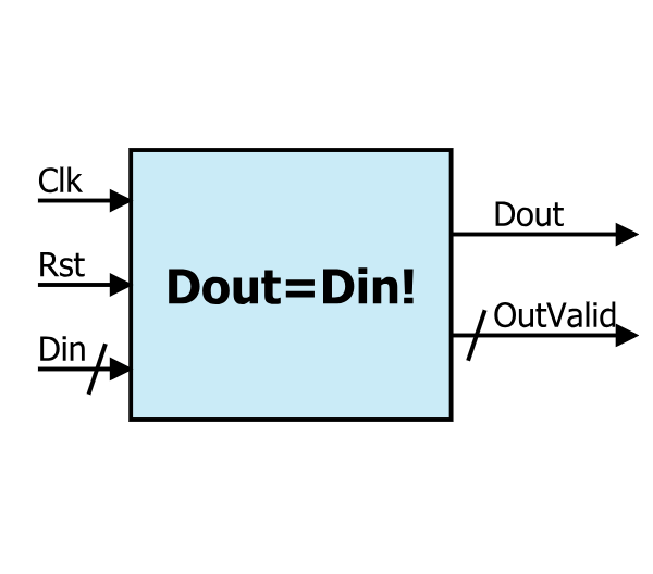
Fonctionnement du composant:
Le composant qui calcule la factorielle est constitué de trois sous composants : un compteur, un multiplieur accumulateur (multiplieur + retard d’un cycle d’horloge) et le circuit d’initialisation. La donnée à l’entrée Din codée sur 5 bits peut prendre des valeurs variant entre 1 et 2^5-1=31. Le circuit permet de calculer la valeur finale de la factorielle après un nombre fini de coups d’horloges. Dès que le résultat est disponible dans le bus de sortie Dout, le circuit positionne la sortie DouReady à ‘1’ pendant un coup d’horloge puis revient à l’état initial ‘0’. Ci-dessous un exemple indiquant la valeur dans le bus de sortie pour Din=7 pour chaque coup d’horloge (front montant), autrement dit la factorielle de 7 (7 !) :
- 1 coup d’horloge : Dout1 = 1
- 2 coup d’horloge : Dout2 = Dout1*2=1*2=2
- 3 coup d’horloge : Dout3 = Dout2*3=1*2*3=2*3=6
- 4 coup d’horloge : Dout4 = Dout3*4=1*2*3*4=6*4=24
- 5 coup d’horloge : Dout5 = Dout4*5=1*2*3*4*5=24*5=120
- 6 coup d’horloge : Dout6 = Dout5*6=1*2*3*4*5*6=120*6=720
- 7 coup d’horloge : Dout7 = Dout6*7=1*2*3*4*5*6*7=720*7= 5040 (voir ici)
Synthèse en VHDL (FactorielN.vhd):
library IEEE;
use IEEE.STD_LOGIC_1164.ALL;


entity FactorielN is
        Generic ( N : positive := 108;
                          M : positive := 5
                        );
    Port ( Rst                 : in  STD_LOGIC;
           Clk                 : in  STD_LOGIC;
           D_in                : in  STD_LOGIC_VECTOR (M-1 downto 0);
           D_out_Ready         : out  STD_LOGIC;
           D_out               : out  STD_LOGIC_VECTOR (N+M-1 downto 0));
end FactorielN;

architecture Behavioral of FactorielN is

signal D_out_CMP_tmp         :   STD_LOGIC :='0';
signal D_out_CMP             :   STD_LOGIC :='0';
signal D_outReady            :   STD_LOGIC :='0';
signal Rst_tmp               :   STD_LOGIC :='0';
signal D_out_count           :   STD_LOGIC_VECTOR (M-1 downto 0):=(others =>'0');
signal D_out_tmp             :   STD_LOGIC_VECTOR (N+M-1 downto 0):=x"000000000000000000000000000" & b"00001";
signal Data_in_A_tmp         :   STD_LOGIC_VECTOR (M-1 downto 0):=b"00001";


-- CMP
COMPONENT CountN
PORT(
        Data_in : IN std_logic_vector(M-1 downto 0);
        Rst : IN std_logic;
        Clk : IN std_logic;
        End_count : OUT std_logic;
        Count_out : OUT std_logic_vector(M-1 downto 0)
        );
END COMPONENT;

COMPONENT MulAccN
PORT(
        Data_in_A : IN std_logic_vector(M-1 downto 0);
        Rst : IN std_logic;
        Clk : IN std_logic;
        Data_out_P : INOUT std_logic_vector(N+M-1 downto 0)
        );
END COMPONENT;


begin

        -- Counter
        Count1: CountN PORT MAP(
                Data_in => D_in,
                Rst => Rst,
                Clk => Clk,
                End_count => D_outReady,
                Count_out => D_out_count
        );

        -- Mul-ACC
        MULACC_1: MulAccN PORT MAP(
                Data_in_A => Data_in_A_tmp,
                Rst => Rst_tmp,
                Clk => Clk,
                Data_out_P => D_out_tmp
        );
        Data_in_A_tmp <= D_out_count;
        Rst_tmp <= D_outReady OR Rst;
        D_out_Ready <= D_outReady;


        -- Latence d'une periode
        P_data_out : process(Rst, Clk)
        begin
                if Rst ='1' then
                        D_out(N+M-1 downto 1) <=(others =>'0');
                        D_out(0) <= '1';
                elsif Clk = '1' and Clk'event then
                        D_out <= D_out_tmp;
                end if;
        end process;

end Behavioral;
Synthèse en VHDL (MulAccN.vhd, CountN, …. ): Voir le fichier ci-dessous
Fichier de simulation en VHDL (tb_FactorielN.vhd):
library ieee;
use ieee.std_logic_1164.all;
use ieee.std_logic_arith.all;
use ieee.std_logic_unsigned.all;
use ieee.numeric_std;


ENTITY tb_FactorielN IS
END tb_FactorielN;

ARCHITECTURE behavior OF tb_FactorielN IS

        -- Component Declaration for the Unit Under Test (UUT)

        COMPONENT FactorielN
        PORT(
                Rst : IN  std_logic;
                Clk : IN  std_logic;
                D_in : IN  std_logic_vector(4 downto 0);
                D_out_Ready : OUT  std_logic;
                D_out : OUT  std_logic_vector(112 downto 0)
                );
        END COMPONENT;


        --Inputs
        signal Rst : std_logic := '1';
        signal Clk : std_logic := '0';
        signal D_in : std_logic_vector(4 downto 0) := b"00001";

        --Outputs
        signal D_out_Ready : std_logic;
        signal D_out : std_logic_vector(112 downto 0);

        -- Clock period definitions
        constant Clk_period : time := 10 ns;

BEGIN

        -- Instantiate the Unit Under Test (UUT)
        uut: FactorielN PORT MAP (
                Rst => Rst,
                Clk => Clk,
                D_in => D_in,
                D_out_Ready => D_out_Ready,
                D_out => D_out
                );

        -- Clock process definitions
        Clk_process :process
        begin
                Clk <= '0';
                wait for Clk_period/2;
                Clk <= '1';
                wait for Clk_period/2;
        end process;

        -- Rst process definitions
        Rst_process :process
        begin
                Rst <= '1';
                wait for Clk_period;

                Rst <= '0';
                wait for 100*Clk_period;
        end process;

        -- Input Data process definitions
        D_in_process :process (Rst, Clk)
        begin

                if Clk = '1' and Clk'event then
                        if Rst ='1' then
                                D_in <= D_in+1;        -- Mise à jour
                        else
                                D_in <= D_in;          -- Mémorisation
                        end if;
                end if;
        end process;
END;
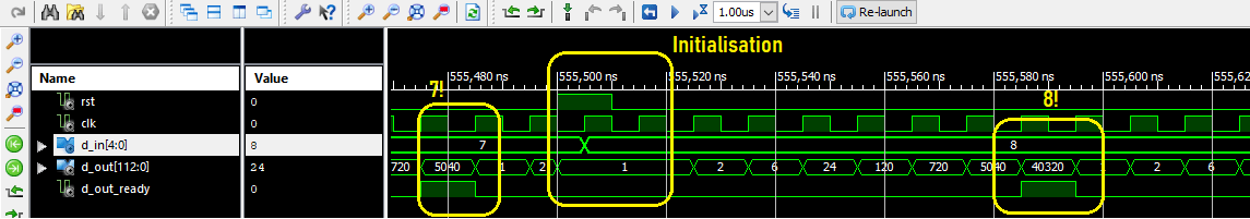
Simulation: Initialisation, 7! et 8! :
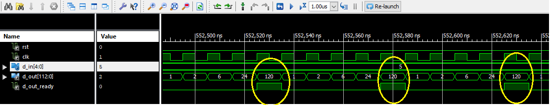
Simulation: 5!:
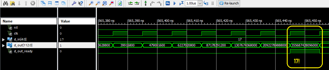
Simulation: 17!:
************
Un petit commentaire de vous, un Grand encouragement pour nous 🙂
************
Téléchargement du projet
************
2 réponses sur « Projet électronique FPGA #7 : Calcul de Factorielle – n! »
[…] PROJET #7 : CALCUL DE FACTORIELLE – N! […]
[…] Voir le projet : Projet électronique FPGA #7 : calcul de factorielle – n! […]