Introduction:
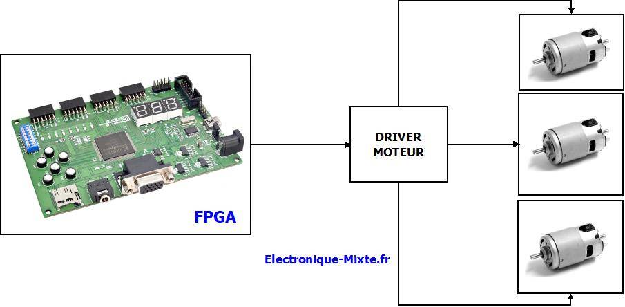
La commande d’un moteur à courant continu est une application type et largement utilisée dans les systèmes motorisés. Dans ce projet, on va étudier d’une façon simple et précise une stratégie de commande de vitesse d’un moteur à courant continu. La méthode est basée sur la variation de la valeur moyenne du signal d’alimentation du moteur à CC en utilisant un signal à modulation de largeur d’impulsion PWM (Pulse Width Modulation). La méthode est utilisable pour diverses puissances d’un moteur à CC.
Objectifs du projet:
- Savoir des notions de base d’un moteur à CC;
- Savoir comment générer un signal triangulaire;
- Savoir comment générer un signal PWM;
- Savoir comment varier la vitesse d’un moteur à CC
- Autres astuces de programmation.
Domaines d’application:
- Robotique ou Drones
- Domotique (ouverture de porte, machine à laver, mixeur …)
- Automobile (voiture électrique, essuie glace, …)
- Applications industrielles divers (système de transmission électromécanique de rotation en translation, tapis roulante, machine du laboratoire de préparation d’échantillon, …)
Pour résumer, les moteurs à CC de petite ou grande puissance, sont utilisés partout dans notre vie quotidienne et ils sont intégrés dans des dispositifs divers avec des degrés de complexité différente. Notez bien que tous les moteurs sont disponibles en différentes tailles et puissances.
Notion de variation de vitesse:
En résume, la variation de vitesse d’un moteur à courant continu, s’opère par la variation de la tension d’alimentation. Il existe des systèmes à base du pont diviseur pour varier la tension d’alimentation (pour des moteurs de petite puissance). L’inconvénient de la méthode, est les pertes joules aux bornes du pont diviseur.
Avant d’entamer la stratégie PWM, on va calculer la valeur moyenne d’un signal logique qui transite entre deux états avec un rapport cyclique paramétré par le paramètre α : Par définition, la valeur moyenne Vmoy d’un signal s(t) est l’intégration du signal dans une période T divisé par la période.
La valeur moyenne Vmoy = αE, varie entre 0 (α=0) et E (α=1). La vitesse de rotation du moteur est proportionnelle à la valeur moyenne Vmoy, donc au paramètre α.
- α=0 : Moteur en arret (vitesse nullee)
- α=1 : Moteur en pleine puissance (vitesse maximale)
La stratégie PWM ou MLI (Modulation de Largeur d’Impulsion), est basée sur le changement du paramètre α et on parle souvent du rapport cyclique. La suite du projet, sera consacrée à la conception d’un composant numérique qui permet de varier le rapport cyclique α du signal, donc la vitesse de rotation du moteur.
Principe du générateur PWM:
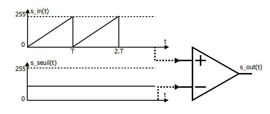
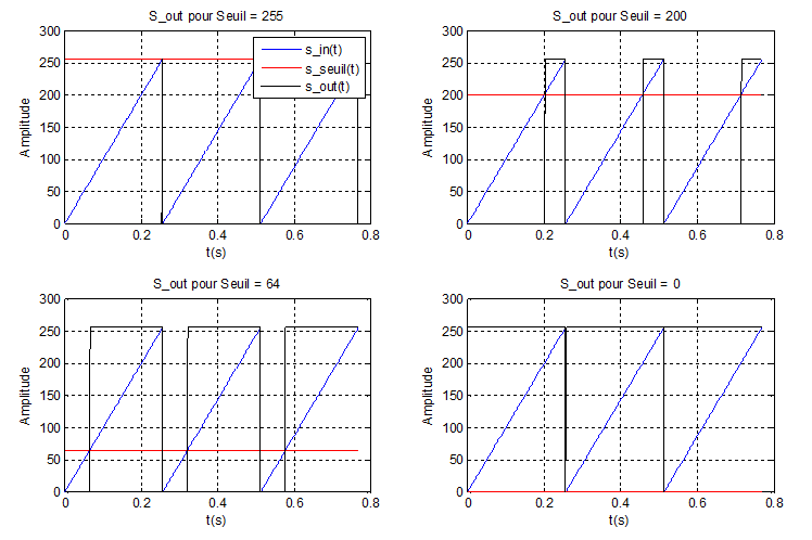
On considère un signal triangulaire s_in(t) code sur 8 bits, non signé et compris entre 0 à 255. On définit une variable fixe qui représente un seuil s_seuil(t), codée sur 8 bits et qui peut prendre une valeur parmi les 256 valeurs. Les figures ci-dessous, montrent la sortie du comparateur s_out(t) pour les différentes valeurs de seuil.
- Graphe 1 : Seuil = 255
- Graphe 2 : Seuil = 200
- Graphe 3 : Seuil = 64
- Graphe 4 : Seuil = 0
On constate que la largeur d’impulsion est minimale pour un seuil de 255 (les conditions du comparateur : « ≥ seuil » au lieu de « > seuil »). La largeur d’impulsion, augmente linéairement pour un seuil décroissant. Pour augmenter la vitesse du moteur, il faut baisser le seuil de déclenchement (Les deux paramètres sont inversement proportionnelles).
Note : Le même principe, est utilisé en électronique analogique, basé sur les amplificateurs opérationnels (minimum deux amplificateurs avec un pont diviseur de tension pour le seuil). Il est faisable également, en prenant le circuit NE555 avec des potentiomètres pour le réglage du rapport cyclique (le seuil).
Synthèse en VHDL :
La synthèse du générateur PWM en VHDL est relativement simple. Le circuit contient trois fonctions de base:
- Générateur du signal triangulaire: Compteur binaire sur N bits (pour N=8 bits on aura 256 combinaison de vitesse)
- Comparateur numérique: Comparateur numérique sur N bits (N=8 bits)
- Générateur d’horloge programmable: Basé sur un compteur binaire afin de varier la fréquence de référence du générateur PWM
Note : Il est intéressant d’avoir une fréquence importante, mais il faut faire attention à la partie puissance et ses limitations en fréquence (hacheur ou driver). Si la fréquence du PWM dépasse la fréquence autorisée par la partie puissance, les transistors risque d’être saturés tout le temps. Cette situation, induit un fonctionnement en plein régime du moteur quelque soit le rapport cyclique (sauf la valeur nulle). De plus, une fréquence importance peut influencer le bon fonctionnement du moteur et générer du bruit.
Ci-dessous le schéma RTL de base pour un canal (Comparateur + Compteur et générateur de fréquence). La variable RapportCyc codé sur 8 bits permet de fixer le seuil de déclenchement du générateur PWM donc le rapport cyclique (voir le programme plus loin).
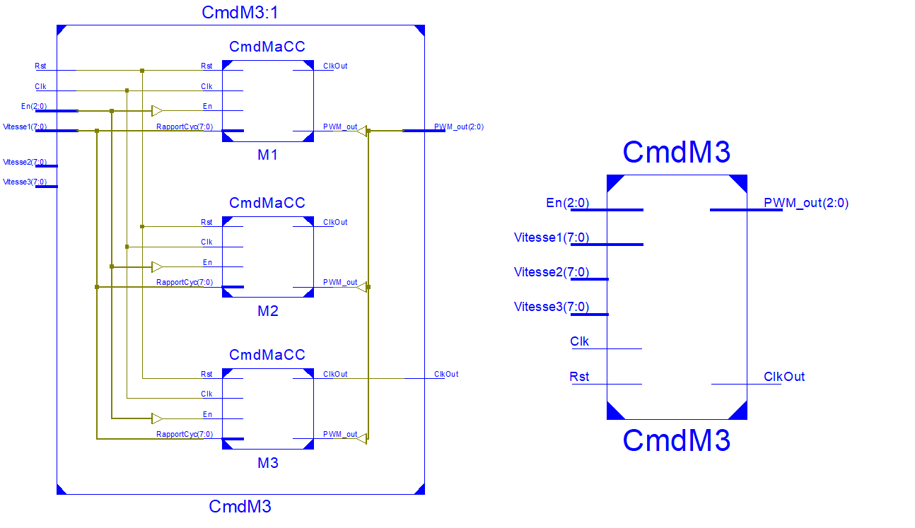
Entité du contrôleur 3 canaux (CmdM3):
- Rst: Entrée d’initialisation
- Clk: Horloge de référence
- En: Entrée d’activation pour les trois canaux (3 signaux EN)
- Vitesse1: Entrée sur 8 bits du rapport cyclique pour le moteur 1
- Vitesse2: Entrée sur 8 bits du rapport cyclique pour le moteur 2
- Vitesse3: Entrée sur 8 bits du rapport cyclique pour le moteur 3
- ClkOut: Sortié d’hologe du générateur PWM
- PWM_out : 3 sorties PWM
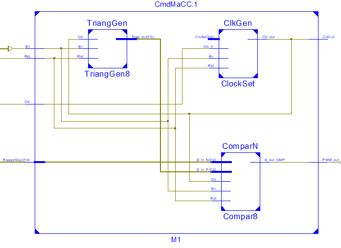
Entité du contrôleur du canal 1 (CmdMaCC):
Programme VHDL du circuit principal CmdM3.vhd:
library IEEE;
use IEEE.STD_LOGIC_1164.ALL;

entity CmdM3 is
    Port ( Rst                 : in  STD_LOGIC;
           Clk                 : in  STD_LOGIC;
           En                 : in  STD_LOGIC_VECTOR (2 downto 0); -- 3 Moteurs
           Vitesse1 : in  STD_LOGIC_VECTOR (7 downto 0);
           Vitesse2 : in  STD_LOGIC_VECTOR (7 downto 0);
           Vitesse3 : in  STD_LOGIC_VECTOR (7 downto 0);
                   ClkOut         : out  STD_LOGIC;
           PWM_out         : out  STD_LOGIC_VECTOR (2 downto 0));
end CmdM3;

architecture Behavioral of CmdM3 is


COMPONENT CmdMaCC
PORT(
        Rst : IN std_logic;
        Clk : IN std_logic;
        En : IN std_logic;
        RapportCyc : IN std_logic_vector(7 downto 0);
        ClkOut : OUT std_logic;
        PWM_out : OUT std_logic
        );
END COMPONENT;

signal ClkOut_1 : std_logic:='0';
signal ClkOut_2 : std_logic:='0';

begin
        M1: CmdMaCC PORT MAP(
                Rst => Rst,
                Clk => Clk,
                En => En(0),
                RapportCyc => Vitesse1,
                ClkOut => ClkOut_1,
                PWM_out => PWM_out(0));

        M2: CmdMaCC PORT MAP(
                Rst => Rst,
                Clk => Clk,
                En => En(1),
                RapportCyc => Vitesse2,
                ClkOut => ClkOut_2,
                PWM_out => PWM_out(1));

        M3: CmdMaCC PORT MAP(
                Rst => Rst,
                Clk => Clk,
                En => En(2),
                RapportCyc => Vitesse3,
                ClkOut => ClkOut,
                PWM_out => PWM_out(2));


end Behavioral;
Programme VHDL du circuit CmdMaCC.vhd:
library IEEE;
use IEEE.STD_LOGIC_1164.ALL;

entity CmdMaCC is
    Port ( Rst : in  STD_LOGIC;
           Clk : in  STD_LOGIC;
           En : in  STD_LOGIC;
           RapportCyc : in  STD_LOGIC_VECTOR (7 downto 0);
                   ClkOut : out  STD_LOGIC;
           PWM_out : out  STD_LOGIC);
end CmdMaCC;

architecture Behavioral of CmdMaCC is

COMPONENT ComparN
PORT(
        Rst : IN std_logic;
        En : IN std_logic;
        Clk : IN std_logic;
        D_in_P : IN std_logic_vector(7 downto 0);
        D_in_N : IN std_logic_vector(7 downto 0);
        D_out_CMP : OUT std_logic
        );
END COMPONENT;


COMPONENT ClkGen
PORT(
        Clk_in : IN std_logic;
        Rst : IN std_logic;
        En : IN std_logic;
        ClkSel : IN std_logic_vector(3 downto 0);
        Clk_out : OUT std_logic
        );
END COMPONENT;

constant ClkSel          : std_logic_vector(3 downto 0):=x"5"; -- 5:OK
signal        Clk_out :  std_logic:='0';
--constant Rst :  std_logic:='0';
--constant En :   std_logic:='1';


COMPONENT TriangGen
PORT(
        Rst : IN std_logic;
        En : IN std_logic;
        Clk : IN std_logic;
        Triag_out : OUT std_logic_vector(7 downto 0)
        );
END COMPONENT;

signal Triag_out :  std_logic_vector(7 downto 0):= (others =>'0');

begin

        ClockSet: ClkGen PORT MAP(
                Clk_in => Clk,
                Rst => Rst,
                En => En,
                ClkSel => ClkSel,
                Clk_out => Clk_out
        );

        TriangGen8: TriangGen PORT MAP(
                Rst => Rst,
                En => En,
                Clk => Clk_out ,
                Triag_out => Triag_out
        );


        Compar8: ComparN PORT MAP(
                Rst => Rst,
                En => En,
                Clk => Clk_out,
                D_in_P => Triag_out,
                D_in_N => RapportCyc,
                D_out_CMP =>PWM_out
        );

        ClkOut <= Clk_out;

end Behavioral;
Programme VHDL du comparateur sur 8 bits ComparN.vhd:
library IEEE;
use IEEE.STD_LOGIC_1164.ALL;


entity ComparN is
        Generic ( N : positive := 8
                        );
    Port ( Rst : in  STD_LOGIC;
           En : in  STD_LOGIC;
           Clk : in  STD_LOGIC;
           D_in_P : in  STD_LOGIC_VECTOR (N-1 downto 0);
           D_in_N : in  STD_LOGIC_VECTOR (N-1 downto 0);
           D_out_CMP : out  STD_LOGIC);
end ComparN;

architecture Behavioral of ComparN is

signal D_out_CMP_tmp :   STD_LOGIC :='0';

begin
        P_cmp : process(Rst, Clk, En )
        begin
                if Clk = '1' and Clk'event then
                        if Rst ='1' then
                                D_out_CMP_tmp <= '0';
                        else
                                if En = '1' then
                                        if D_in_P > D_in_N then
                                                D_out_CMP_tmp <= '1';
                                        else
                                                D_out_CMP_tmp <= '0';
                                        end if ;
                                else
                                        D_out_CMP_tmp <= D_out_CMP_tmp;
                                end if;
                        end if;
                end if;
        end process P_cmp;
        D_out_CMP <= D_out_CMP_tmp;

end Behavioral;
Programme VHDL du générateur triangulaire sur 8 bits TriangGen.vhd:
library IEEE;
use IEEE.STD_LOGIC_1164.ALL;
use ieee.std_logic_unsigned.all;


entity TriangGen is
        Generic ( N  : positive := 8
                        );
    Port ( Rst : in  STD_LOGIC;
           En : in  STD_LOGIC;
           Clk : in  STD_LOGIC;
           Triag_out : out  STD_LOGIC_VECTOR (N-1 downto 0));
end TriangGen;

architecture Behavioral of TriangGen is

signal TriagG_tmp :   STD_LOGIC_VECTOR (N-1 downto 0):= (others =>'0');

begin
        P_TriagG : process(Rst, Clk, En )
        begin
                if Clk = '1' and Clk'event then
                        if Rst ='1' then
                                TriagG_tmp <= (others =>'0');
                        else
                                if En = '1' then
                                        TriagG_tmp <= TriagG_tmp+1;
                                else
                                        TriagG_tmp <= TriagG_tmp;
                                end if;
                        end if;
                end if;
        end process P_TriagG;
        Triag_out <= TriagG_tmp;

end Behavioral;
Programme VHDL du diviseur de fréquence ClkGen.vhd:
library ieee;
use ieee.std_logic_1164.all;
use ieee.std_logic_unsigned.all;


entity ClkGen is
    Port ( Clk_in : in  STD_LOGIC;
                   Rst : in  STD_LOGIC;
           En : in  STD_LOGIC;
                   ClkSel : in  STD_LOGIC_VECTOR (3 downto 0);
           Clk_out : out  STD_LOGIC);
end ClkGen;

architecture Behavioral of ClkGen is

signal ClkSel_tmp :   STD_LOGIC_VECTOR (3 downto 0):=(others =>'0');
signal Clk_out_tmp :   STD_LOGIC:='0';
signal Count_tmp : STD_LOGIC_VECTOR (25 downto 0):=(others =>'0');

begin
        P_ClkOut : process(Rst, Clk_in, En, ClkSel_tmp )
        begin
                if Clk_in = '1' and Clk_in'event then
                        if Rst ='1' then
                                Clk_out_tmp <= '0';
                        else
                                if En = '1' then

                                        -- Sélection d'une sortie du compteur (division par 2^N)
                                        case ClkSel_tmp is

                                                when x"0"         => Clk_out_tmp <= Count_tmp(1);
                                                when x"1"         => Clk_out_tmp <= Count_tmp(2);
                                                when x"2"         => Clk_out_tmp <= Count_tmp(3);
                                                when x"3"         => Clk_out_tmp <= Count_tmp(4);
                                                when x"4"         => Clk_out_tmp <= Count_tmp(5);
                                                when x"5"         => Clk_out_tmp <= Count_tmp(6);
                                                when x"6"         => Clk_out_tmp <= Count_tmp(7);
                                                when x"7"         => Clk_out_tmp <= Count_tmp(8);
                                                when x"8"         => Clk_out_tmp <= Count_tmp(9);
                                                when x"9"         => Clk_out_tmp <= Count_tmp(10);
                                                when x"A"         => Clk_out_tmp <= Count_tmp(11);
                                                when x"B"         => Clk_out_tmp <= Count_tmp(12);
                                                when x"C"         => Clk_out_tmp <= Count_tmp(13);
                                                when x"D"         => Clk_out_tmp <= Count_tmp(14);
                                                when x"E"         => Clk_out_tmp <= Count_tmp(15);
                                                when x"F"         => Clk_out_tmp <= Count_tmp(16);

                                                when others => Clk_out_tmp <= Count_tmp(0);
                                        end case ;
                                else
                                        Clk_out_tmp <= Clk_out_tmp;
                                end if;
                        end if;
                end if;
        end process;
        Clk_out <= Clk_out_tmp;
        ClkSel_tmp <= ClkSel;

        P_count : process(Rst, Clk_in, En )
        begin
                if Clk_in = '1' and Clk_in'event then
                        if Rst ='1' then
                                Count_tmp <= (others =>'0');
                        else
                                if En = '1' then
                                        Count_tmp <= Count_tmp+1;
                                else
                                        Count_tmp <= Count_tmp;
                                end if;
                        end if;
                end if;
        end process;


end Behavioral;
Programme VHDL de simulation (3 canaux validés pour 3 vitesses) tb_CmdM3.vhd:
LIBRARY ieee;
USE ieee.std_logic_1164.ALL;


ENTITY tb_CmdM3 IS
END tb_CmdM3;

ARCHITECTURE behavior OF tb_CmdM3 IS

    -- Component Declaration for the Unit Under Test (UUT)

    COMPONENT CmdM3
    PORT(
         Rst                 : IN  std_logic;
         Clk                 : IN  std_logic;
         En                 : IN  std_logic_vector(2 downto 0);
         Vitesse1         : IN  std_logic_vector(7 downto 0);
         Vitesse2         : IN  std_logic_vector(7 downto 0);
         Vitesse3         : IN  std_logic_vector(7 downto 0);
         ClkOut         : OUT  std_logic;
         PWM_out         : OUT  std_logic_vector(2 downto 0)
        );
    END COMPONENT;


   --Inputs
   signal Rst : std_logic := '0';
   signal Clk : std_logic := '0';
   signal En : std_logic_vector(2 downto 0) := (others => '0');
   signal Vitesse1 : std_logic_vector(7 downto 0) := (others => '0');
   signal Vitesse2 : std_logic_vector(7 downto 0) := (others => '0');
   signal Vitesse3 : std_logic_vector(7 downto 0) := (others => '0');

         --Outputs
   signal ClkOut : std_logic;
   signal PWM_out :  std_logic_vector(2 downto 0);

   -- Clock period definitions
   constant Clk_period : time := 10 ns;
   constant ClkOut_period : time := 10 ns;

BEGIN


        -- Instantiate the Unit Under Test (UUT)
        uut: CmdM3 PORT MAP (
                Rst => Rst,
                Clk => Clk,
                En => En,
                Vitesse1 => Vitesse1,
                Vitesse2 => Vitesse2,
                Vitesse3 => Vitesse3,
                ClkOut => ClkOut,
                PWM_out => PWM_out
                );

        -- Clock process definitions
        Clk_process :process
        begin
                Clk <= '0';
                wait for Clk_period/2;
                Clk <= '1';
                wait for Clk_period/2;
        end process;

        En <= b"111";
        Rst <= '0';

        Vitesse1 <= x"0f";
        Vitesse2 <= x"3f";
        Vitesse3 <= x"f0";

END;
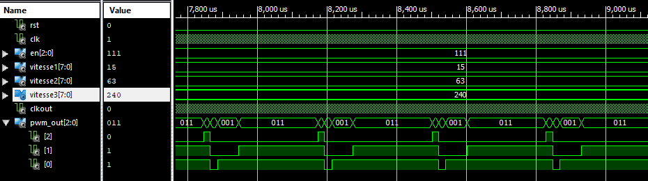
Résultats de simulation:
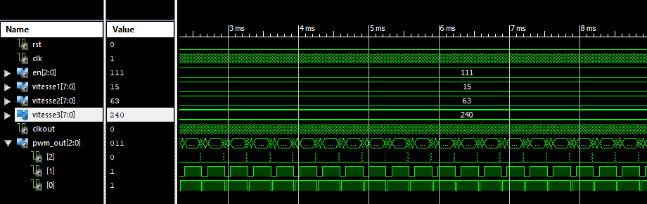
Dans la partie implimentation, on considère uniquement le rapport cyclique 1 pour les trois moteurs afin de réduire le nombre des entrées (8 entrées au lieu de 8×3). Il ne faut pas oublier de remplacer la variable Vitesse2 et Vitesse3 par Vitesse1 dans la ligne (RapportCyc => Vitesse1) au m moment de l’instanciation pour les deux composants M2 et M3 (voir le fichier CmdM3.vhd). En résumé, le signal Vitesse1 sert à Controller les trois moteurs au même temps durant la phase de test sur carte.
Schéma électrique du câblage:
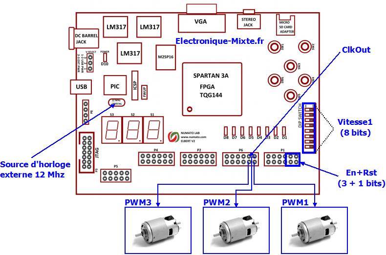
Fichier de câblageavec les pins physique du circuit FPGA pinout_CmdM3.ucf:
# Alimentation
CONFIG VCCAUX = "3.3" ;

# Horloge de référence de 12 MHz
NET "Clk"        LOC = P129  | IOSTANDARD = LVCMOS33 | PERIOD = 12MHz;

# Rapport cyclique (vitesse) [ 8 Interrupteurs]
NET "Vitesse1[0]"         LOC = P70   | PULLUP  | IOSTANDARD = LVCMOS33 | SLEW = SLOW | DRIVE = 12;
NET "Vitesse1[1]"         LOC = P69   | PULLUP  | IOSTANDARD = LVCMOS33 | SLEW = SLOW | DRIVE = 12;
NET "Vitesse1[2]"         LOC = P68   | PULLUP  | IOSTANDARD = LVCMOS33 | SLEW = SLOW | DRIVE = 12;
NET "Vitesse1[3]"         LOC = P64   | PULLUP  | IOSTANDARD = LVCMOS33 | SLEW = SLOW | DRIVE = 12;
NET "Vitesse1[4]"         LOC = P63   | PULLUP  | IOSTANDARD = LVCMOS33 | SLEW = SLOW | DRIVE = 12;
NET "Vitesse1[5]"         LOC = P60   | PULLUP  | IOSTANDARD = LVCMOS33 | SLEW = SLOW | DRIVE = 12;
NET "Vitesse1[6]"         LOC = P59   | PULLUP  | IOSTANDARD = LVCMOS33 | SLEW = SLOW | DRIVE = 12;
NET "Vitesse1[7]"         LOC = P58   | PULLUP  | IOSTANDARD = LVCMOS33 | SLEW = SLOW | DRIVE = 12;

# Entrées de selection des moteurs (activation du controlleur) + RST
NET "En[0]"                LOC = P31   | IOSTANDARD = LVCMOS33 | SLEW = SLOW | DRIVE = 12;
NET "En[1]"                LOC = P32   | IOSTANDARD = LVCMOS33 | SLEW = SLOW | DRIVE = 12;
NET "En[2]"                LOC = P28   | IOSTANDARD = LVCMOS33 | SLEW = SLOW | DRIVE = 12;
NET "Rst"                  LOC = P30   | IOSTANDARD = LVCMOS33 | SLEW = SLOW | DRIVE = 12;


# Sorties PWM + Sortie d'horloge PWM
NET "PWM_out[0]"        LOC = P19   | IOSTANDARD = LVCMOS33 | SLEW = SLOW | DRIVE = 12;
NET "PWM_out[1]"        LOC = P21   | IOSTANDARD = LVCMOS33 | SLEW = SLOW | DRIVE = 12;
NET "PWM_out[2]"        LOC = P18   | IOSTANDARD = LVCMOS33 | SLEW = SLOW | DRIVE = 12;
NET "ClkOut"            LOC = P20   | IOSTANDARD = LVCMOS33 | SLEW = SLOW | DRIVE = 12;
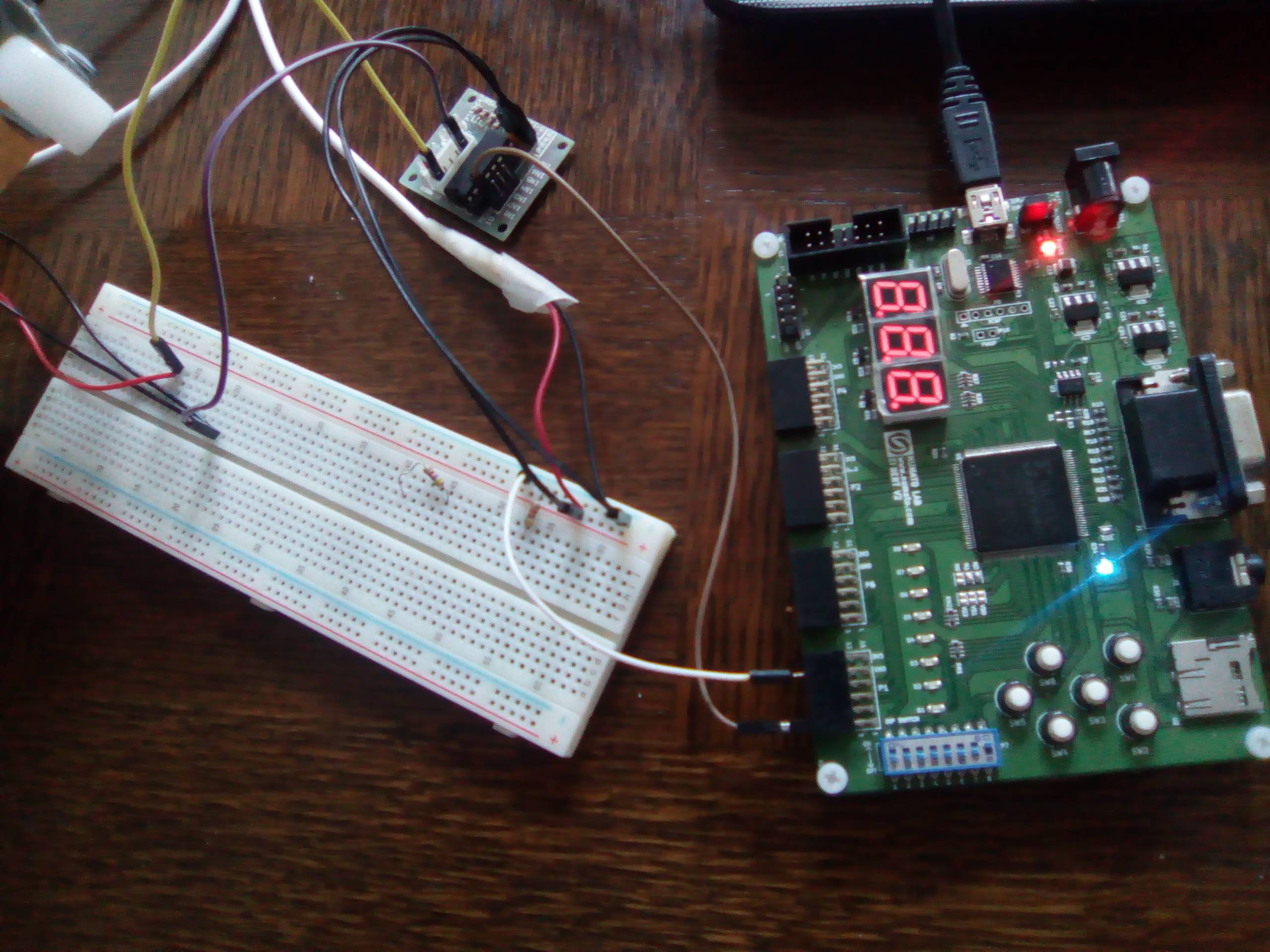
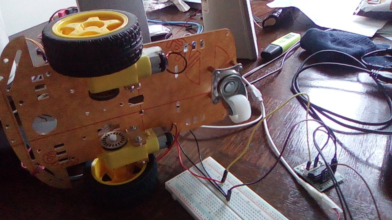
Photos du projet:
************
Un petit commentaire de vous, un Grand encouragement pour nous 🙂
************
Téléchargement du projet
************
3 réponses sur « Projet électronique FPGA #6 : Commande synchrone multicanaux d’un moteur à CC »
« La vitesse de rotation du moteur et proportionnelle à la valeur moyenne Vmoy, donc au paramètre α »
Il faut remplacer « et » par « est » 🙂
Super! Merci 🙂
[…] PROJET ÉLECTRONIQUE FPGA #6 : COMMANDE SYNCHRONE MULTICANAUX D’UN MOTEUR À CC […]