Découvrez notre Chaîne YouTube "Ingénierie et Projets"
Découvrez notre Chaîne Secondaire "Information Neuronale et l'Ingénierie du Cerveau"

Projet électronique FPGA 5 Générateur des signaux V1 - photos projets (2)

Objectifs du projet électronique

  • Comprendre le principe de fonctionnement de la méthode utilisée
  • Savoir comment coder un signal en virgule fixe sur N bits de taille M
  • Savoir comment stocker un signal en virgule fixe sur la mémoire de FPGA
  • Savoir comment générer une horloge d’échenillage à une fréquence fixe à partir d’une horloge Maitre
  • Se familiariser avec un système multi processus
  • Savoir comment concevoir sa propre Convertisseur D/A (DAC) de résolution R avec le réseau R/2R
  • Savoir comment implémenter un code sur FPGA

Principe de fonctionnement

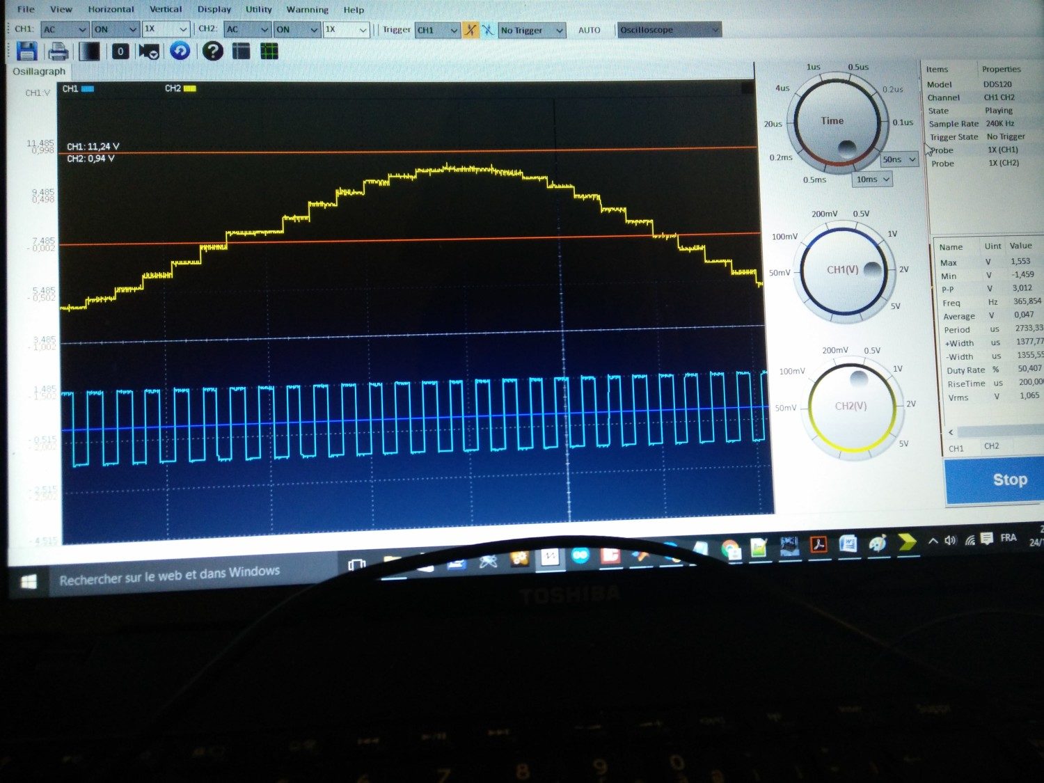
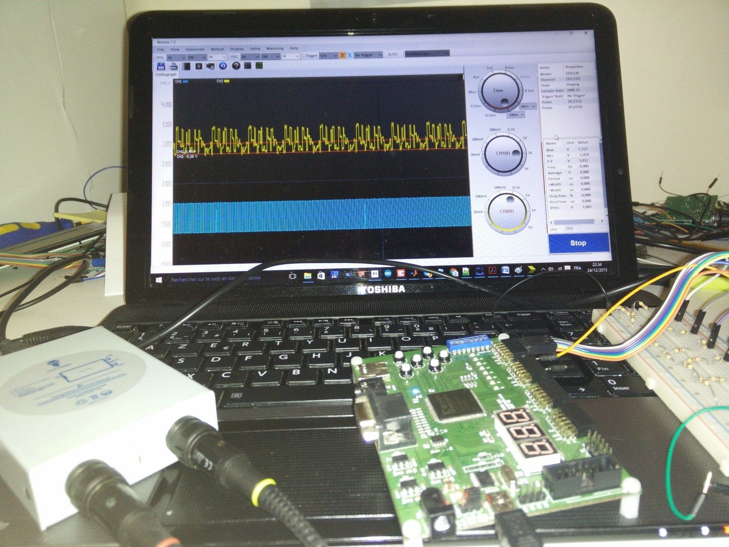
Le circuit permet de générer trois signaux multiplexés en fonction du choix de l’utilisateur codés sur 8 bits (signal sinusoïdal, bruit ou la somme des deux). La fréquence d’échantillonnage est fixe et peuvent être modifie manuellement dans le programme principal. Le circuit comprend également trois entrées de sélection des signaux, une entrée de validation, une entrée de réinitialisation du circuit et trois LED indicateurs du signal sélectionne.
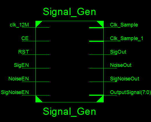
Projet électronique FPGA 5 Générateur des signaux V1 - RTL

 Les entrées :

  • Clk_12M : Horloge système de 12 MHz
  • CE : Entre de validation du circuit (Chip Select)
  • RST : Entrée de réinitialisation
  • SigEN : Activation du signal sinusoïdal
  • NoiseEN : Activation du bruit
  • SigNoiseEN : Activation du signal sinusoïdal + bruit

 Les sorties :

  • Clk_Sample : Horloge de l’échantillonnage (dérivée de l’horloge maitre) liée avec une LED
  • Clk_Sample_1 : Equivalent à l’horloge Clk_Sample, liée avec un IO du kit de développement (signal externe peut être visualisé ou exploité pour synchroniser les échantillons de la sortie numérique
  • SigOut : Indicateur de l’activation du signal sinusoïdal lié avec une LED
  • NoiseOut : Indicateur de l’activation du bruit lié avec une LED
  • SigNoiseOut : Indicateur de l’activation du signal sinusoïdal + bruit lié avec une LED
  • OutputSignal : Signal de sortie sur 8 bits (1 échantillon sur 8 bits pour chaque coup d’horloge Clk_Sample )

Le principe du générateur des signaux est très simple ! Il est basé sur le stockage d’une période du signal sinusoïdal codée sur N bits, dans notre cas N=7 (valeurs variées de 0 à 127) de longueur 32 c.à.d. un tableau de taille 32 qui contient des valeurs qui variées de 0 à 127. Donc afin d’afficher une période du signal il faut 32 coup d’horloge !

Ex : Si on veut générer un signal sinusoïdal de fréquence F0, alors il faut que la fréquence d’échantillonnage soit 32 fois supérieure à la fréquence du signal.

Fs=N(32)*F0

Tant que le nombre des échantillons constituant le signal est important, la qualité du signal est meilleur en revanche il faut une fréquence plus rapide par rapport à la fréquence du signal. On prend comme exemple le nombre d’échantillons égal à 255 (tableau de 255 valeurs), pour obtenir un signal sinusoïdal de 1KHz il faut que la fréquence d’échantillonnage égale à 255 KHz !

Le nombre d’échantillons important induit utilisation excessif des ressources en temps et physique (horloge et mémoire).

Comment coder un signal en virgule fixe sur N bits de taille M ?

Vous pouvez  en 3 ou 4 lignes de codes sur matlab passer d’un signal sinusoïdal flottant en code hexadécimal directement implémenté sur FPGA en virgule fixe. Vous pouvez choisir n’importe quel type du signal (sin, cos, sinc, bruit…). Dans ce projet on va se limiter sur deux types du signal : signal sinusoïdal et une séquence pseudo-aléatoire (un nombre limité des échantillons d’une distribution gaussienne).

Dans ce projet on va se limiter sur deux types du signal : signal sinusoïdal et une séquence pseudo-aléatoire (un nombre limité des échantillons d’une distribution gaussienne).

Le code VHDL contient trois vecteurs de 32 échantillons :

  • Un vecteur du signal sinusoïdal (0-127)
  • Deux vecteurs du bruit (0-15, 0-63) (bruit faible, bruit fort)

Code matlab pour générer un signal sinusoïdal 

% Sin
t=linspace(0,1,32);
s_t=(sin(2*pi*t)+1)/2;
s_n=round((2^7-1)*s_t);
s_hex=dec2hex(s_n);

% Bruit faible
b_t=rand(1,32);
b_n=round((2^4-1)*b_t);
b_hex=dec2hex(s_n);

% Bruit fort
b_t=rand(1,32);
b_n=round((2^6-1)*b_t);
b_hex=dec2hex(s_n);

Savoir comment générer une horloge

Vous pouvez consulter le projet électronique FPGA 3 : Générateur des horloges. Le circuit permet de générer une multitude des horloges allant de 6 MHz à 1 Hz, 8 horloges en total.

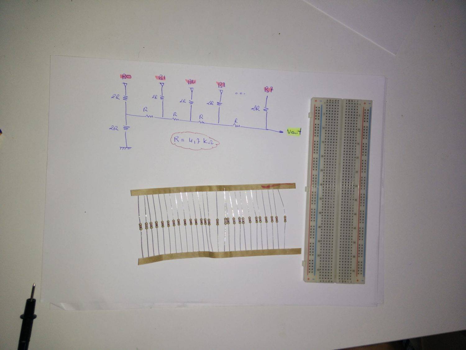
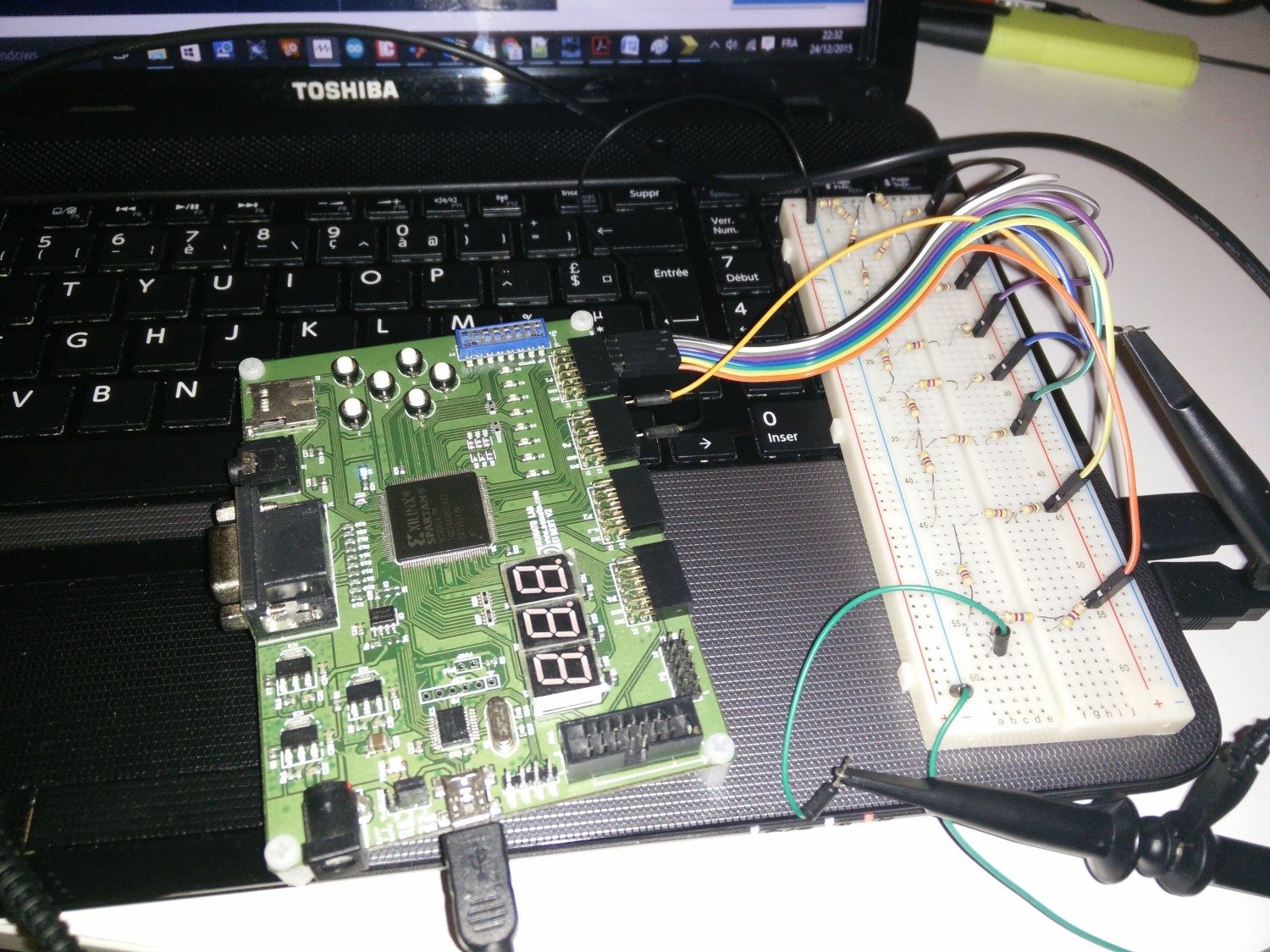
Le circuit Convertisseur A/D avec le réseau R/2R

Un Projet : Générateur des signaux à base du PIC16877 à fréquence fixe & DAC 8 bits R/2R traite le principe du fonctionnement du convertisseur A/D avec le réseau R/2R.

Afin de réduire la consommation du courant dans les pins de FPGA, j’ai utilisé une résistances de 4.7KR. La valeur minimale de la résistance dépend du courant max supporté par le pin IO du FPGA.

Projet électronique FPGA 5 Générateur des signaux V1 - DAC (2)

Projet électronique FPGA 5 Générateur des signaux V1 - DAC (1)

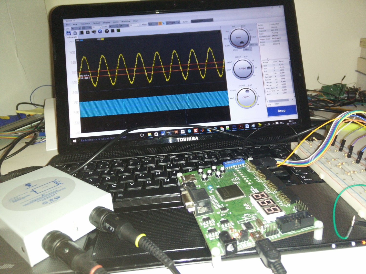
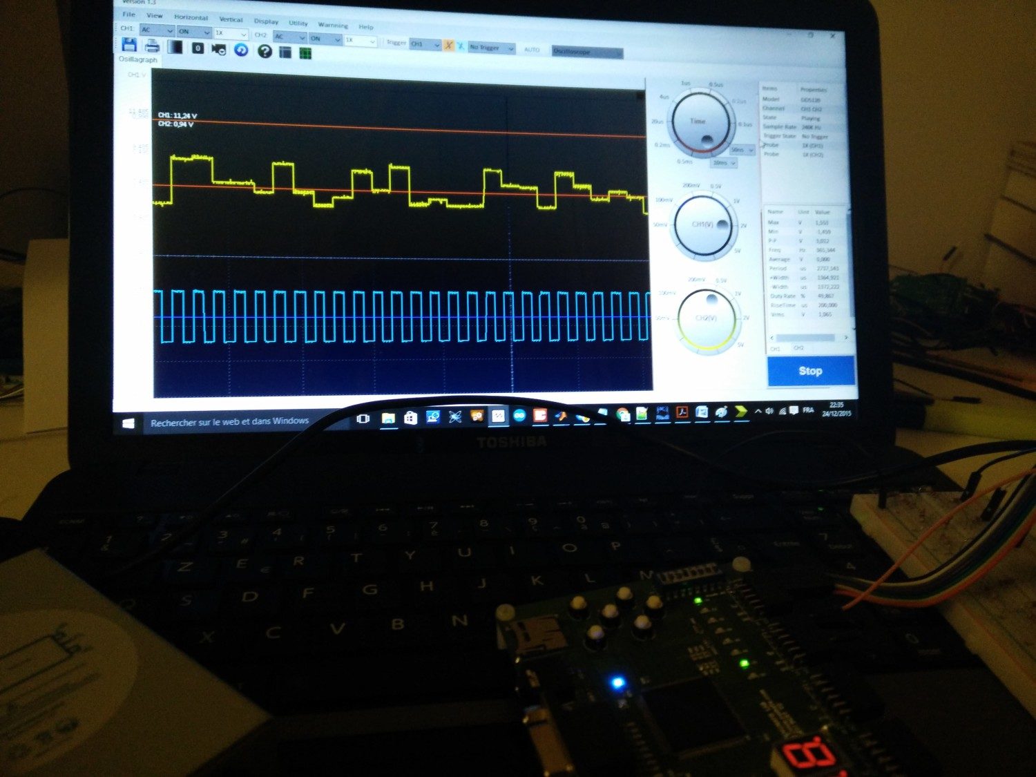
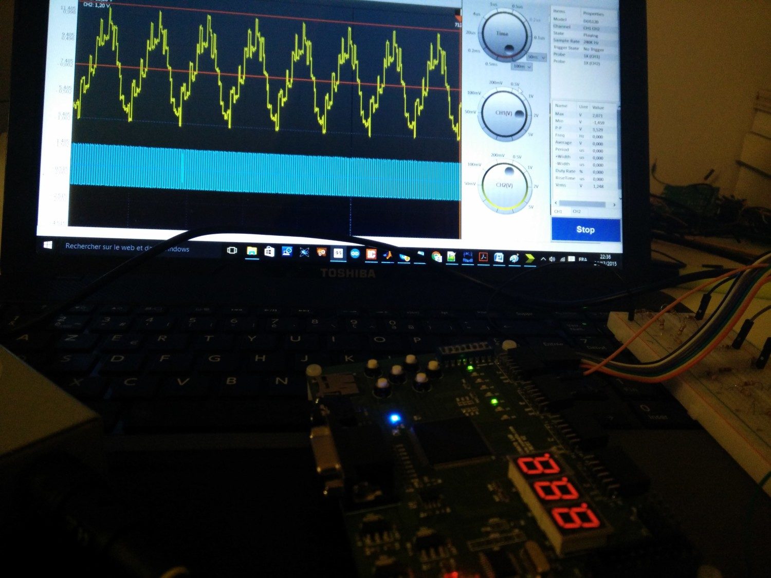
Oscilloscope numérique

Pour les personnes qui m‘ont posées la question sur l’outil de visualisation des signaux, j’utilise un oscilloscope numérique avec une câble USB de 20 MHz de bande, deux canaux. L’instrument est léger et pratique pour débuter ses projets, il est menu d’une interface graphique simple et pratique. Vous pouvez accéder à la description détaillée en cliquant sur l’image ci-dessous ou Lien direct.
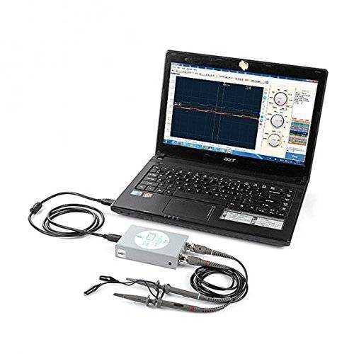
Osciloscope numérique - digital oscilloscope

Programme FPGA

library ieee;
use ieee.std_logic_1164.all;
use ieee.std_logic_arith.all;
use ieee.std_logic_unsigned.all;
use ieee.numeric_std;


entity Signal_Gen is
        Generic
   (
      N : positive :=24;
                M : positive :=32
   );

    Port (

           clk_12M         : in  STD_LOGIC;
           CE                         : in  STD_LOGIC:='0';
           RST                 : in  STD_LOGIC:='0';

           Clk_Sample         : out  STD_LOGIC :='0';
           Clk_Sample_1         : out  STD_LOGIC :='0';

           SigEN : in  STD_LOGIC:='0';
           NoiseEN : in  STD_LOGIC:='0';
           SigNoiseEN : in  STD_LOGIC:='0';

           SigOut : out  STD_LOGIC:='0';
           NoiseOut : out  STD_LOGIC:='0';
           SigNoiseOut : out  STD_LOGIC:='0';
           OutputSignal : out  STD_LOGIC_VECTOR (7 downto 0):= x"00");

end Signal_Gen;

architecture Behavioral of Signal_Gen is

SIGNAL    Count_Sample_tmp : std_logic_vector(N-1 downto 0):= x"000000";
SIGNAL    Clk_Sample_tmp : std_logic:='0';

SIGNAL   Signal_tmp :   STD_LOGIC_VECTOR (7 downto 0);
SIGNAL   Noise_tmp :   STD_LOGIC_VECTOR (7 downto 0);

TYPE     T_DATA is array (0 to M-1) of std_logic_vector(7 downto 0);
SIGNAL   sel : std_logic_vector(7 downto 0):=x"00";

CONSTANT SIN_V : T_DATA := -- Signal sin
(x"40",
x"4C",
x"59",
x"64",
x"6E",
x"75",
x"7B",
x"7E",
x"7F",
x"7D",
x"79",
x"72",
x"69",
x"5E",
x"53",
x"46",
x"39",
x"2C",
x"21",
x"16",
x"0D",
x"06",
x"02",
x"00",
x"01",
x"04",
x"0A",
x"11",
x"1B",
x"26",
x"33",
x"3F");

--CONSTANT NOISE_V : T_DATA := -- 4 bits (bruit faible
--(x"0C",
--x"0E",
--x"02",
--x"0E",
--x"09",
--x"01",
--x"04",
--x"08",
--x"0E",
--x"0E",
--x"02",
--x"0F",
--x"0E",
--x"07",
--x"0C",
--x"02",
--x"06",
--x"0E",
--x"0C",
--x"0E",
--x"0A",
--x"01",
--x"0D",
--x"0E",
--x"0A",
--x"0B",
--x"0B",
--x"06",
--x"0A",
--x"03",
--x"0B",
--x"00");

CONSTANT NOISE_V : T_DATA := -- 6 bits (bruit fort)
(
x"10",
x"32",
x"1B",
x"39",
x"0B",
x"11",
x"09",
x"09",
x"37",
x"25",
x"23",
x"09",
x"36",
x"27",
x"16",
x"20",
x"19",
x"05",
x"0F",
x"08",
x"0C",
x"0F",
x"1A",
x"03",
x"39",
x"3C",
x"1F",
x"1F",
x"15",
x"39",
x"17",
x"07");


--CONSTANT NOISE_V : T_DATA :=( "",);

begin

-- PROCESS INDEX INCRIMENT

        PROCESS (Clk_Sample_tmp,sel,RST)
                BEGIN
                        IF RST = '1' THEN
                                Noise_tmp <= x"00";
                        ELSIF (Clk_Sample_tmp'EVENT AND Clk_Sample_tmp='1') THEN
                                CASE sel IS
                                        WHEN x"00" => Noise_tmp<=NOISE_V(0);         Signal_tmp<= SIN_V(0);
                                        WHEN x"01" => Noise_tmp<=NOISE_V(1);         Signal_tmp<= SIN_V(1);
                                        WHEN x"02" => Noise_tmp<=NOISE_V(2);         Signal_tmp<= SIN_V(2);
                                        WHEN x"03" => Noise_tmp<=NOISE_V(3);         Signal_tmp<= SIN_V(3);
                                        WHEN x"04" => Noise_tmp<=NOISE_V(4);         Signal_tmp<= SIN_V(4);
                                        WHEN x"05" => Noise_tmp<=NOISE_V(5);         Signal_tmp<= SIN_V(5);
                                        WHEN x"06" => Noise_tmp<=NOISE_V(6);         Signal_tmp<= SIN_V(6);
                                        WHEN x"07" => Noise_tmp<=NOISE_V(7);         Signal_tmp<= SIN_V(7);
                                        WHEN x"08" => Noise_tmp<=NOISE_V(8);         Signal_tmp<= SIN_V(8);
                                        WHEN x"09" => Noise_tmp<=NOISE_V(9);         Signal_tmp<= SIN_V(9);
                                        WHEN x"0A" => Noise_tmp<=NOISE_V(10);        Signal_tmp<= SIN_V(10);
                                        WHEN x"0B" => Noise_tmp<=NOISE_V(11);        Signal_tmp<= SIN_V(11);
                                        WHEN x"0C" => Noise_tmp<=NOISE_V(12);        Signal_tmp<= SIN_V(12);
                                        WHEN x"0D" => Noise_tmp<=NOISE_V(13);        Signal_tmp<= SIN_V(13);
                                        WHEN x"0E" => Noise_tmp<=NOISE_V(14);        Signal_tmp<= SIN_V(14);
                                        WHEN x"0F" => Noise_tmp<=NOISE_V(15);        Signal_tmp<= SIN_V(15);
                                        WHEN x"10" => Noise_tmp<=NOISE_V(16);        Signal_tmp<= SIN_V(16);
                                        WHEN x"11" => Noise_tmp<=NOISE_V(17);        Signal_tmp<= SIN_V(17);
                                        WHEN x"12" => Noise_tmp<=NOISE_V(18);        Signal_tmp<= SIN_V(18);
                                        WHEN x"13" => Noise_tmp<=NOISE_V(19);        Signal_tmp<= SIN_V(19);
                                        WHEN x"14" => Noise_tmp<=NOISE_V(20);        Signal_tmp<= SIN_V(20);
                                        WHEN x"15" => Noise_tmp<=NOISE_V(21);        Signal_tmp<= SIN_V(21);
                                        WHEN x"16" => Noise_tmp<=NOISE_V(22);        Signal_tmp<= SIN_V(22);
                                        WHEN x"17" => Noise_tmp<=NOISE_V(23);        Signal_tmp<= SIN_V(23);
                                        WHEN x"18" => Noise_tmp<=NOISE_V(24);        Signal_tmp<= SIN_V(24);
                                        WHEN x"19" => Noise_tmp<=NOISE_V(25);        Signal_tmp<= SIN_V(25);
                                        WHEN x"1A" => Noise_tmp<=NOISE_V(26);        Signal_tmp<= SIN_V(26);
                                        WHEN x"1B" => Noise_tmp<=NOISE_V(27);        Signal_tmp<= SIN_V(27);
                                        WHEN x"1C" => Noise_tmp<=NOISE_V(28);        Signal_tmp<= SIN_V(28);
                                        WHEN x"1D" => Noise_tmp<=NOISE_V(29);        Signal_tmp<= SIN_V(29);
                                        WHEN x"1E" => Noise_tmp<=NOISE_V(30);        Signal_tmp<= SIN_V(30);
                                        WHEN x"1F" => Noise_tmp<=NOISE_V(31);        Signal_tmp<= SIN_V(31);
                                        WHEN OTHERS => Noise_tmp<=NOISE_V(0);        Signal_tmp<= SIN_V(0);
                                END CASE ;
                   END IF;
        END PROCESS;

-- Incrémentation chaque coup d'horloge
-- de la valeur de la sélection [Compteur de 0 à 31 ]

        PROCESS (Clk_Sample_tmp, RST,CE)
                BEGIN
                 IF RST ='1' THEN
                        sel <= x"00";
                 ELSIF (Clk_Sample_tmp'EVENT AND Clk_Sample_tmp='1') THEN
                        IF CE ='1' THEN
                                sel<= sel + 1 ;
                                IF sel = x"1F" THEN
                                        sel<= x"00";
                                END IF ;
                        ELSE
                                sel<=sel;
                        END IF;
                 END IF ;
        END PROCESS;

-- Générateur des clocks de 6 MHh ----> 11Hz

        PROCESS (clk_12M, RST,CE)
                BEGIN
                 IF RST ='1' THEN
                        Count_Sample_tmp <= x"000000"; --(others =>'0')
                 ELSIF (clk_12M'EVENT AND clk_12M='1') THEN
                        IF CE ='1' THEN
                                Count_Sample_tmp<= Count_Sample_tmp + 1 ;
                        ELSE
                                Count_Sample_tmp<=Count_Sample_tmp;
                        END IF;
                 END IF ;
        END PROCESS;

        -- Changez l'indice pour augmenter ou diminuer la fréquence
        -- Indice varié de 0(fréquence maximale) à 23 (fréquence minimale)
        -- L'horloge est une division de la fréquence maître de 6 MHz

        Clk_Sample_tmp<=Count_Sample_tmp(N-10);
        Clk_Sample<=Count_Sample_tmp(N-10);
        Clk_Sample_1<=Count_Sample_tmp(N-10);

-- Process de sélection du type du signal

        PROCESS (clk_12M, RST,SigEN,NoiseEN,SigNoiseEN)
                BEGIN
                 IF RST ='1' THEN
                        SigOut <='0';
         NoiseOut <='0';
         SigNoiseOut <='0';
                        OutputSignal<=x"00";

                 ELSIF (clk_12M'EVENT AND clk_12M='1') THEN
                        IF SigEN ='1' THEN
                                SigOut <='1';
                                NoiseOut <='0';
                                SigNoiseOut <='0';
                                OutputSignal<=Signal_tmp;

                        ELSIF NoiseEN ='1' THEN
                                SigOut <='0';
                                NoiseOut <='1';
                                SigNoiseOut <='0';
                                OutputSignal<=Noise_tmp;

                        ELSIF SigNoiseEN  ='1' THEN
                                SigOut <='0';
                                NoiseOut <='0';
                                SigNoiseOut <='1';
                                OutputSignal<= Signal_tmp + Noise_tmp;
                        ELSE
                                SigOut<='0';
                                NoiseOut <='0';
                                SigNoiseOut <='0';
                                OutputSignal<=x"00";

                        END IF;
                 END IF ;
        END PROCESS;


end Behavioral;

Contenue du fichier ucf (Pinout)

CONFIG VCCAUX = "3.3" ;

# Clock 12 MHz
NET "clk_12M"                  LOC = P129  | IOSTANDARD = LVCMOS33 | PERIOD = 12MHz;

# Inputs DIP Swithch

NET "CE"                        LOC = P70   | PULLUP  | IOSTANDARD = LVCMOS33 | SLEW = SLOW | DRIVE = 12;
NET "RST"                       LOC = P69   | PULLUP  | IOSTANDARD = LVCMOS33 | SLEW = SLOW | DRIVE = 12;
NET "SigEN"                     LOC = P68   | PULLUP  | IOSTANDARD = LVCMOS33 | SLEW = SLOW | DRIVE = 12;
NET "NoiseEN"                   LOC = P64   | PULLUP  | IOSTANDARD = LVCMOS33 | SLEW = SLOW | DRIVE = 12;
NET "SigNoiseEN"                LOC = P63   | PULLUP  | IOSTANDARD = LVCMOS33 | SLEW = SLOW | DRIVE = 12;

# Outputs LED

NET "SigOut"                    LOC = P46   | IOSTANDARD = LVCMOS33 | SLEW = SLOW | DRIVE = 12;
NET "NoiseOut"                  LOC = P47   | IOSTANDARD = LVCMOS33 | SLEW = SLOW | DRIVE = 12;
NET "SigNoiseOut"               LOC = P48   | IOSTANDARD = LVCMOS33 | SLEW = SLOW | DRIVE = 12;
NET "Clk_Sample"                LOC = P55   | IOSTANDARD = LVCMOS33 | SLEW = SLOW | DRIVE = 12;

# Output Signal
NET "OutputSignal[0]"           LOC = P31   | IOSTANDARD = LVCMOS33 | SLEW = SLOW | DRIVE = 12;
NET "OutputSignal[1]"           LOC = P32   | IOSTANDARD = LVCMOS33 | SLEW = SLOW | DRIVE = 12;
NET "OutputSignal[2]"           LOC = P28   | IOSTANDARD = LVCMOS33 | SLEW = SLOW | DRIVE = 12;
NET "OutputSignal[3]"           LOC = P30   | IOSTANDARD = LVCMOS33 | SLEW = SLOW | DRIVE = 12;
NET "OutputSignal[4]"           LOC = P27   | IOSTANDARD = LVCMOS33 | SLEW = SLOW | DRIVE = 12;
NET "OutputSignal[5]"           LOC = P29   | IOSTANDARD = LVCMOS33 | SLEW = SLOW | DRIVE = 12;
NET "OutputSignal[6]"           LOC = P24   | IOSTANDARD = LVCMOS33 | SLEW = SLOW | DRIVE = 12;
NET "OutputSignal[7]"           LOC = P25   | IOSTANDARD = LVCMOS33 | SLEW = SLOW | DRIVE = 12;

# Clock
NET "Clk_Sample_1"              LOC = P19   | IOSTANDARD = LVCMOS33 | SLEW = SLOW | DRIVE = 12;

Photos du projet

Projet-électronique-FPGA-5-Générateur-des-signaux-V1-photos-projets-1-1500x1125

Projet électronique FPGA 5 Générateur des signaux V1 - photos projets (2)


Projet-électronique-FPGA-5-Générateur-des-signaux-V1-photos-projets-4-1500x1125


Projet-électronique-FPGA-5-Générateur-des-signaux-V1-photos-projets-3-1500x1125


Projet-électronique-FPGA-5-Générateur-des-signaux-V1-photos-projets-5-1500x1125


Projet-électronique-FPGA-5-Générateur-des-signaux-V1-photos-projets-7-1500x1125

************

Un petit commentaire de vous, un Grand encouragement pour nous 🙂

************

Click to rate this post!
[Total: 1 Average: 5]

1 commentaire

Projet électronique : Traitement du signal avec Arduino # Lissage & Seuillage d’un signal 3/3 - FPGA | Arduino | Matlab | Cours · 2018-09-09 à 7:21

[…] Voir le projet pour plus des détails : Projet électronique FPGA #5 : Générateur des signaux #V1 […]

Laisser un commentaire

Avatar placeholder

Votre adresse e-mail ne sera pas publiée. Les champs obligatoires sont indiqués avec *

Anti-Robot *

We use cookies to personalise content and ads, to provide social media features and to analyse our traffic. We also share information about your use of our site with our social media, advertising and analytics partners.
Cookies settings
Accept
Decline
Privacy & Cookie policy
Privacy & Cookies policy
Cookie name Active

Privacy Policy

What information do we collect?

We collect information from you when you register on our site or place an order. When ordering or registering on our site, as appropriate, you may be asked to enter your: name, e-mail address or mailing address.

What do we use your information for?

Any of the information we collect from you may be used in one of the following ways: To personalize your experience (your information helps us to better respond to your individual needs) To improve our website (we continually strive to improve our website offerings based on the information and feedback we receive from you) To improve customer service (your information helps us to more effectively respond to your customer service requests and support needs) To process transactions Your information, whether public or private, will not be sold, exchanged, transferred, or given to any other company for any reason whatsoever, without your consent, other than for the express purpose of delivering the purchased product or service requested. To administer a contest, promotion, survey or other site feature To send periodic emails The email address you provide for order processing, will only be used to send you information and updates pertaining to your order.

How do we protect your information?

We implement a variety of security measures to maintain the safety of your personal information when you place an order or enter, submit, or access your personal information. We offer the use of a secure server. All supplied sensitive/credit information is transmitted via Secure Socket Layer (SSL) technology and then encrypted into our Payment gateway providers database only to be accessible by those authorized with special access rights to such systems, and are required to?keep the information confidential. After a transaction, your private information (credit cards, social security numbers, financials, etc.) will not be kept on file for more than 60 days.

Do we use cookies?

Yes (Cookies are small files that a site or its service provider transfers to your computers hard drive through your Web browser (if you allow) that enables the sites or service providers systems to recognize your browser and capture and remember certain information We use cookies to help us remember and process the items in your shopping cart, understand and save your preferences for future visits, keep track of advertisements and compile aggregate data about site traffic and site interaction so that we can offer better site experiences and tools in the future. We may contract with third-party service providers to assist us in better understanding our site visitors. These service providers are not permitted to use the information collected on our behalf except to help us conduct and improve our business. If you prefer, you can choose to have your computer warn you each time a cookie is being sent, or you can choose to turn off all cookies via your browser settings. Like most websites, if you turn your cookies off, some of our services may not function properly. However, you can still place orders by contacting customer service. Google Analytics We use Google Analytics on our sites for anonymous reporting of site usage and for advertising on the site. If you would like to opt-out of Google Analytics monitoring your behaviour on our sites please use this link (https://tools.google.com/dlpage/gaoptout/)

Do we disclose any information to outside parties?

We do not sell, trade, or otherwise transfer to outside parties your personally identifiable information. This does not include trusted third parties who assist us in operating our website, conducting our business, or servicing you, so long as those parties agree to keep this information confidential. We may also release your information when we believe release is appropriate to comply with the law, enforce our site policies, or protect ours or others rights, property, or safety. However, non-personally identifiable visitor information may be provided to other parties for marketing, advertising, or other uses.

Registration

The minimum information we need to register you is your name, email address and a password. We will ask you more questions for different services, including sales promotions. Unless we say otherwise, you have to answer all the registration questions. We may also ask some other, voluntary questions during registration for certain services (for example, professional networks) so we can gain a clearer understanding of who you are. This also allows us to personalise services for you. To assist us in our marketing, in addition to the data that you provide to us if you register, we may also obtain data from trusted third parties to help us understand what you might be interested in. This ‘profiling’ information is produced from a variety of sources, including publicly available data (such as the electoral roll) or from sources such as surveys and polls where you have given your permission for your data to be shared. You can choose not to have such data shared with the Guardian from these sources by logging into your account and changing the settings in the privacy section. After you have registered, and with your permission, we may send you emails we think may interest you. Newsletters may be personalised based on what you have been reading on theguardian.com. At any time you can decide not to receive these emails and will be able to ‘unsubscribe’. Logging in using social networking credentials If you log-in to our sites using a Facebook log-in, you are granting permission to Facebook to share your user details with us. This will include your name, email address, date of birth and location which will then be used to form a Guardian identity. You can also use your picture from Facebook as part of your profile. This will also allow us and Facebook to share your, networks, user ID and any other information you choose to share according to your Facebook account settings. If you remove the Guardian app from your Facebook settings, we will no longer have access to this information. If you log-in to our sites using a Google log-in, you grant permission to Google to share your user details with us. This will include your name, email address, date of birth, sex and location which we will then use to form a Guardian identity. You may use your picture from Google as part of your profile. This also allows us to share your networks, user ID and any other information you choose to share according to your Google account settings. If you remove the Guardian from your Google settings, we will no longer have access to this information. If you log-in to our sites using a twitter log-in, we receive your avatar (the small picture that appears next to your tweets) and twitter username.

Children’s Online Privacy Protection Act Compliance

We are in compliance with the requirements of COPPA (Childrens Online Privacy Protection Act), we do not collect any information from anyone under 13 years of age. Our website, products and services are all directed to people who are at least 13 years old or older.

Updating your personal information

We offer a ‘My details’ page (also known as Dashboard), where you can update your personal information at any time, and change your marketing preferences. You can get to this page from most pages on the site – simply click on the ‘My details’ link at the top of the screen when you are signed in.

Online Privacy Policy Only

This online privacy policy applies only to information collected through our website and not to information collected offline.

Your Consent

By using our site, you consent to our privacy policy.

Changes to our Privacy Policy

If we decide to change our privacy policy, we will post those changes on this page.
Save settings
Cookies settings

You have successfully subscribed to the newsletter

There was an error while trying to send your request. Please try again.

FPGA | Arduino | Matlab | Cours will use the information you provide on this form to be in touch with you and to provide updates and marketing.