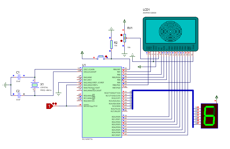
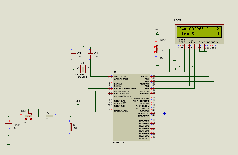
Description du montage :
Le montage est constitué d’un afficheur LCD graphique de dimensions 128×64 (Data Sheet GLCD), le microcontrôleur PIC16F877A et un afficheur BCD 7 Segments.
Routine d’interruption :
Un bouton poussoir est raccordé avec la broche B0 du port B, Le front montant de RB0 permet de déclencher une interruption.La routine d’interruption sert à afficher des valeurs de 0 à 9 sur l’afficheur BCD 7 Segments puis retourner au programme principal.
Le programme principale :
Le programme principal permet d’afficher en continue (boule fermée) une image statique, du texte puis des cercles avec des rayons différents.
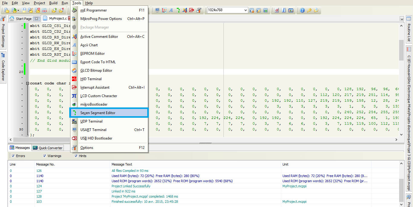
Comment convertir une valeur BCD 7 Segment en valeur décimal (ou hexadécimal) ?
Le programme MikroC dispose d’un outils très simple pour effectuer la conversions des valeurs BCD 7 Segments en valeur Décimales.
1. Click sur Tools ===> Seven Segment Editor
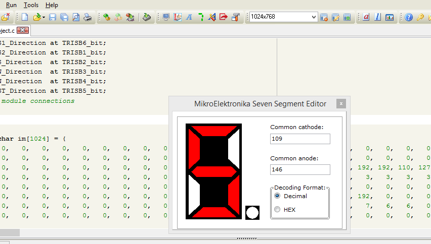
2. Tracez la valeur et copier le code en décimal en fonction de votre Afficheur (Cathode ou Anode commune)
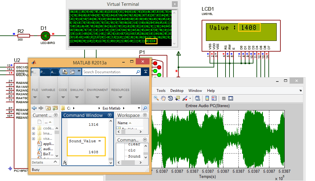
Script matlab pour convertir une image en image compatible avec GLCD
% Dimensions de GLCD
GLCD_clos=128;
GLCD_rows= 64;

% Intensité de l'image entre 0-1
Intensite = 0.4 ;

% Lecture de l'image
im_in =imread('imTest.jpg');

% Redimensionnement de l'image
im_in=imresize(im_in,[GLCD_rows GLCD_clos]);

% Conversion de l'image en Niveau de Gris
imGray= rgb2gray(im_in);

% Conversion de l'image en image monochromatique
imOut = im2bw(imGray,maps, Intensite);

% Enregistrement de la nouvelle image
imwrite(imOut,'imBMPOut.bmp');
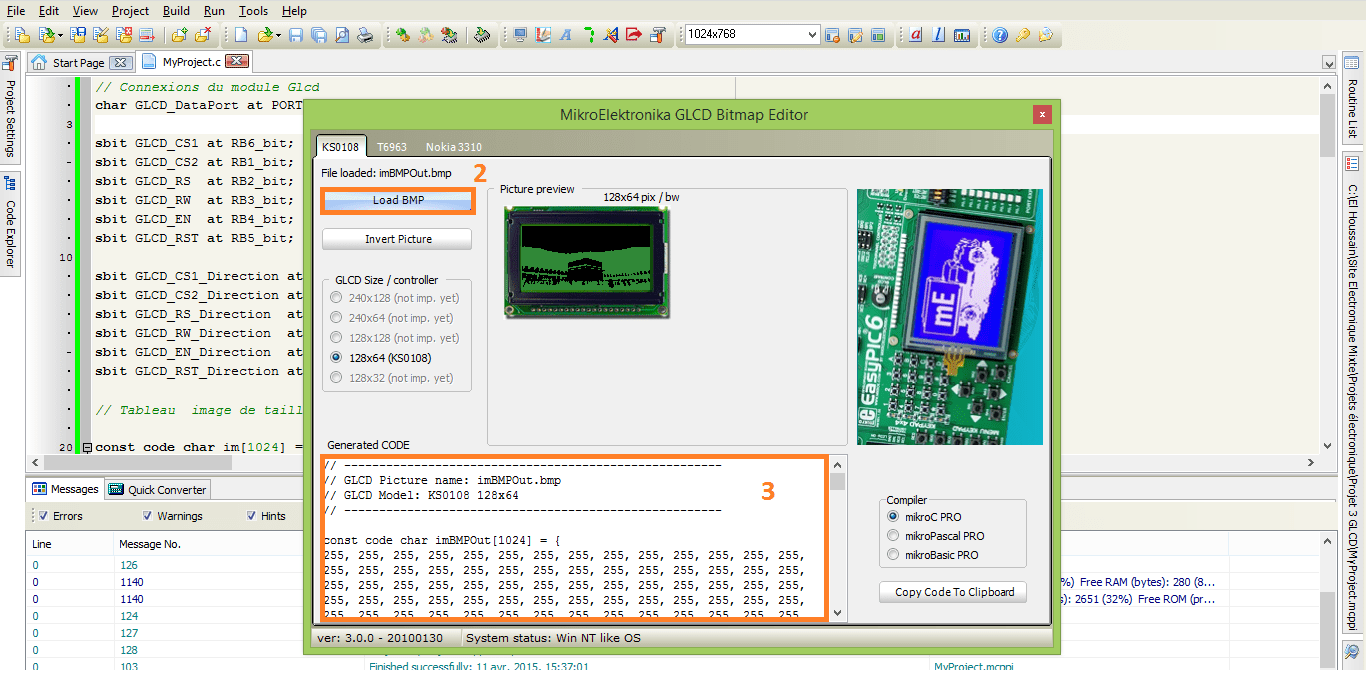
Comment intégrer une image sur MikroC ?
1. Click sur Tools ===> GLCD Bitmap Editor
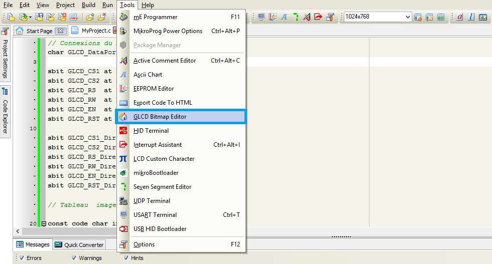
2. Click sur Load BMP
3. Copier/Coller le code dans votre interface de programmation MikroC
Code MikroC
// Connexions du module GLCD
char GLCD_DataPort at PORTD;

sbit GLCD_CS1 at RB6_bit;
sbit GLCD_CS2 at RB1_bit;
sbit GLCD_RS  at RB2_bit;
sbit GLCD_RW  at RB3_bit;
sbit GLCD_EN  at RB4_bit;
sbit GLCD_RST at RB5_bit;

sbit GLCD_CS1_Direction at TRISB6_bit;
sbit GLCD_CS2_Direction at TRISB1_bit;
sbit GLCD_RS_Direction  at TRISB2_bit;
sbit GLCD_RW_Direction  at TRISB3_bit;
sbit GLCD_EN_Direction  at TRISB4_bit;
sbit GLCD_RST_Direction at TRISB5_bit;

// Tableau  image de taille 1024

const code char im[1024] = { 0,   0,   2,   2,   1,   1,   1,   1,   0,   0,   0,   1,   0,   0,   0,   0...
};

// Tableau des valeurs BCD pour l'afficheur BCD 7 Segments (0-9)
unsigned short ValSeg[10]={192,207,164,176  ,153  ,146 , 130 , 248 , 128 , 144};
int i ;

// Programme d'interruption PB0
void interrupt ()
{
     int j;

     // Désactiver toutes les interruptions
     INTCON.INTE=0;

     // Si l'indicateur PB0 est active
     if(INTCON.INTF)
     {
         // Effacer l'indicateur de l'interruption PB0
         INTCON.INTF=0;
         for(j=0;j<10;j++)
           {
               PORTC =ValSeg[j] & 0x7F;
               delay_ms(300);
           }
           PORTC =192 & 0x7F;
      }

      // Réactiver les interruptions
      INTCON.INTE=1;
}

void main()
{
  TRISE=0x00;
  TRISC=0x00;
  TRISB=0x01;

  PORTC= 192;

  // Validation de l'interruption
  OPTION_REG.INTEDG=1;
  INTCON.GIE=1;
  INTCON.INTE=1;

  // Effacer l'indicateur de l'interruption PB0
  INTCON.INTF=0;

  // Initialisation de GLCD
  Glcd_Init();

  // Effacer GLCD
  Glcd_Fill(0x00);

  while(1)
  {
      // Afficher l'image sur GLCD
      Glcd_Image(im);
      delay_ms(2000);
      Glcd_Fill(0x00);

      // Afficher 10 cercles de rayons différents au centre de GLCD
      for (i = 1; i <= 10; i++)
         Glcd_Circle(63,32, 3*i, 1);

      delay_ms(2000);
      Glcd_Fill(0x00);

      // Afficher le texte sur chaque page (8 pages)
      for(i=0;i<7;i++)
      {
          Glcd_Write_Text("Electronique-Mixte.Fr", 0, i, 1);
          delay_ms(1000);
      }

      Glcd_Fill(0x00);
  }

}
Télécharger gratuitement le fichier du projet : Afficheur graphique GLCD 64×128 à base du PIC16F877 et interruption
merci . merci
c’est vraiment intéressent! Merci infiniment pour le grand travail que vous avez fourni